Das Rig einrichten
Raum und Bühne
Für einen realistischen Eindruck und eine bessere Orientierung lassen sich verschiedene feste Elemente hinzufügen.
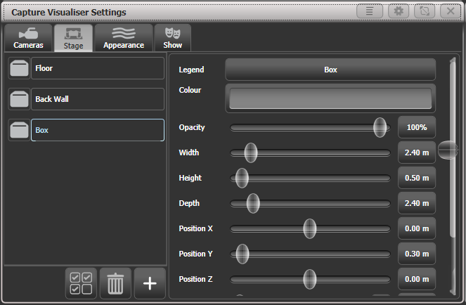
Öffnen Sie das Fenster Capture Visualiser Settings per Doppelklick auf Open/View und wählen Capture Visualiser Settings, oder durch einen Klick auf den Kontext-Button Open Settings im Capture Visualiser-Fenster). Klicken Sie nun oben auf den Reiter Stage.

Die Elemente "Floor" (Boden) und "Back Wall" (Rückwand) sind bereits eingerichtet. Klickt man links unten auf das + (Pluszeichen), so können weitere Objekte hinzugefügt werden.
Klicken Sie links auf eines der vorhandenen Objekte, so können seine Eigenschaften mit den Fadern und Input-Boxen rechts bearbeitet werden: so können Sie die Objekte positionieren und in der Größe verändern. Ebenso können Sie rechts oben Farbe und Bezeichnung der Objekte verändern.
Geräte/Fixtures hinzufügen und einrichten
Ist die Funktion "Auto Update" aktiviert (zu finden auf dem Reiter Show im Fenster Capture Settings), so werden Geräte beim Patchen in der Titan-Software automatisch zur Capture-Bühne hinzugefügt.
Wird eine Show aus einer früheren Titan-Version geladen, so werden die Geräte/Fixtures nicht automatisch zu Capture hinzugefügt. Dazu ist zunächst ein Updaten der Personalities erforderlich: Patch Edit Fixtures Update Personality Update All. Auch ein Gerätetausch (Exchange Fixtures) kann helfen.
Geräte werden, sobald sie in Capture vorhanden sind, mit den Rädern (Encodern) positioniert. Wählen Sie dazu ein oder mehrere Geräte oder ein Gerätegruppe aus und drücken Sie Locate. Mit dem Kontext-Button Position - Orientation wird die Steuerung für Position und Orientierung der jeweils ausgewählten Geräte auf die Wheels gelegt. Das Gleiche passiert, wenn man den Rad-Modus mit der Menütaste G auf „Räder = Visualiser" schaltet.
Wählen Sie mit den Attribut-Tasten Position, so können Sie nun die X/Y/Z-Position der gewählten Fixtures einstellen. Sind mehrere Geräte gewählt, so lassen sich mit der Fan-Taste oder der Option Scale-Fan die Geräte gleichmäßig verteilen/auffächern. Auch die Optionen Split, Curve, Group der Fan-Funktion funktionieren wie gewohnt.
Klicken Sie auf das Display oberhalb der Encoder, so können Sie ebenfalls die betreffenden Werte schrittweise verändern. Für die Rotation erfolgt das in 45°-Schritten.
Wenn man von vorn auf die Bühne schaut, so ist die Orientierung von XYZ wie folgt:
| Achse | Beschreibung |
|---|---|
| X | bewegt nach rechts/links |
| Y | bewegt nach oben/unten |
| Z | bewegt nach vorn/hinten |
Klickt man nochmals auf Position, so schalten die Encoder auf Orientation. Damit können die Geräte um die X/Y/Z-Achse gedreht/geschwenkt werden. Auch hierbei kann der Fan-Modus verwendet werden.
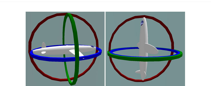
Die XYZ-Rotation kann man sich am besten vorstellen, wenn man von einer kardanischen Aufhängung, einem sog. Gimbal, ausgeht: drei Ringe sind ineinander drehbar gelagert (siehe linkes Bild unten). Dabei kann es dazu kommen, dass zwei Achsen scheinbar das Gleich machen, womit bestimmte Orientierungen nicht mehr erreicht werden können. Dieser Zustand ist bekannt als sog. Gimbal Lock und entsteht dann, wenn zwei Achsen (durch Drehung der dritten um 90°) zusammenfallen (Bild unten rechts). Verändern Sie in diesem Falle die dritte Achse um 90°, damit wieder alle Freiheitsgrade zur Verfügung stehen und alle Orientierungen erreicht werden können.

Illustration by MathsPoetry
Betätigen Sie Position ein drittes Mal, so können Sie die Rotation verändern. Sind nur einzelne Geräte ausgewählt, hat das die gleiche Wirkung wie Orientation. Sind dagegen mehrere Geräte angewählt, so rotiert die Gruppe als Ganzes um ihren Mittelpunkt.
Es empfiehlt sich, zunächst die Geräte im Tilt etwas aus der Mitte zu fahren, so dass man beim Ändern der Orientierung sieht, wohin man gerade dreht. Außerdem empfiehlt es sich, zumindest ein richtiges Gerät zum Vergleich anzuschließen, um zu überprüfen, dass alle Richtungen und Positionierungen im richtigen Sinn erfolgen.
Kameras einrichten (Ansichten)
Es stehen vier Kameras - unabhängige Ansichten - zur Verfügung, wobei weitere hinzugefügt werden können.
Die entsprechenden Optionen stehen über das Kontext-Menü zur Verfügung.

Die Steuerung der Kameras erfolgt im Fenster Capture Visualiser Settings: zum Öffnen drücken Sie zweimal auf
View / Open und wählen Capture Settings von den Buttons, oder Sie verwenden den Kontext-Button Open Settings des Capture-Fensters.Die Steuerung der Kameras erfolgt ebenfalls im Fenster Capture Visualiser Settings auf dem Reiter 'Cameras'.
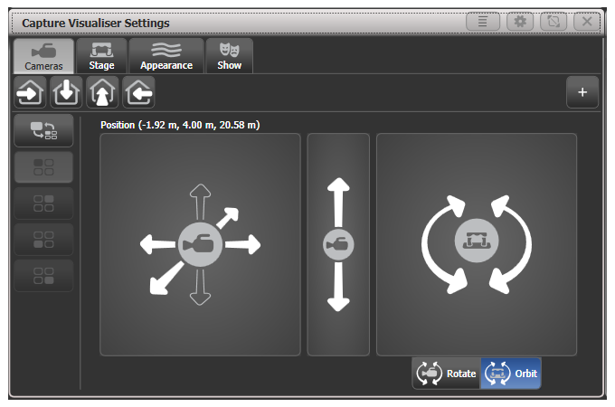
Mit den vier Schaltflächen oben lassen sich die verschiedenen Kameras umschalten (siehe unten); klickt man rechts auf das +, kann man weitere Kameras hinzufügen.

Der obere Button der linken Spalte schaltet zwischen der Ansicht mit einer oder mit vier Kameras um. Ist die Vierer-Ansicht aktiv, so schalten die vier Buttons darunter zwischen den einzelnen Teilansichten um.
Mit der linken Fläche kann man die Kamera rechts/links sowie nach vorn/hinten positionieren.
Mit der mittleren Fläche verschiebt man die Kamera nach oben/unten.
Rechts kann man die Kamera drehen und schwenken; der jeweilige Modus wir mit den Buttons darunter gewählt:
Rotate: dreht die Kamera nach links/rechts/oben/unten
Orbit: schwenkt die Kamera im Kreis um die Bühne, wobei sie stets auf den gleichen Punkt ausgerichtet bleibt.
Klickt man auf den Kontext-Button Move Camera, so kann man die Kamera mit den Rädern bewegen sowie im Menü Set Coordinates die Position/Rotation numerisch eingeben.
Klickt man auf den Kontext-Button Rotate Camera oder \{Orbit Camera\}, so kann man die Kamera mit den Rädern drehen/schwenken, sowie die Rotation numerisch eingeben.
Capture Darstellungs-Optionen
Der Reiter Appearance (Darstellung) im Fenster Capture Visualiser Settings bietet folgende Einstellmöglichkeiten:
- Ambient lighting (Umgebungslicht)
- Smoke density (Nebel/Haze; bei Capture heißt das "Atmosphere")
- Smoke variation ("Atmosphere contrast" - Mix zwischen statischem Dunst und sich bewegendem Nebel - 0%=Haze, 100%=Nebel)
- Smoke speed ("Atmosphere speed" - Nebel/Haze Geschwindigkeit)
- Exposure adjustment (Belichtung, die Empfindlichkeit der Kamera)
- Bloom amount (eine Rendereinstellung, die die Darstellung heller Lichtquellen beeinflusst)
- Rendering settings detail (Render Details Stufe): Qualität der Darstellung. Eine höhere Stufe erzeugt eine bessere Darstellung, niedrige Stufen nehmen weniger Rechenleistung in Anspruch.